Forced air cooling is to enhance the air
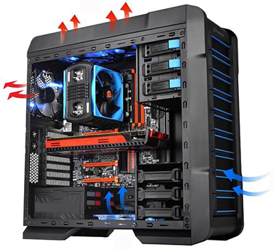
movement so as to realize the cooling approach that is required by the heat sources. There are two approaches to quickly realize better cooling performance and these include increasing the cooling surface area of the heat sources and increasing the air velocity when it flows through an object. The first approach of increasing the cooling surface area can be realized by installing heat sinks on the surface of the heat sources. Typically, a heat sink is firmly fixed on the heat source so as to obtain better cooling performance. The second approach of enhancing airflow can be realized by installing fans (wind turbines) to enhance ventilation and strengthen the cooling effect. Under most scenarios, adding a fan onto a heat sink can greatly enhance the cooling efficiency.
Forced air cooling is often used for the cooling of internal combustion engines. As we can see from the exterior of an internal combustion engine on a vehicle or motorcycle, there are fins and an exhaust guard for forced air cooling. The reason for the exterior fins is to increase the cooling area and the fan inside the exhaust guard is to enhance the airflow through the surface of the internal combustion engine so that the temperature of the engine can be reduced quickly to ensure normal operation.
In recent years, Winshare Thermal has been strengthening our research and development on the applications of forced air cooling techniques. We have realized our forced air cooling on wind power converters, PV inverters, and SVG high power machines. The cooling combination of high power skived fin heat sink + fans or high power skived fin heat sink + heat pipe can greatly enhanced the cooling performance.
Air cooling + extruded heat sinks
Air cooling +friction stir welded heat sinks
Air cooling +stitched fin heat sinks
Air cooling +skived fin heat sinks
Air cooling +heat pipe heat sinks
Design inputs, specifications and requirements:
|
Loss
|
Single loss
(W)
|
Number of devices
|
Total losses
(W)
|
Model number
|
Ambient temperatu
(℃)
|
Cooling design temperature(℃)
|
|
IGBT Module
|
426W
|
1
|
426W
|
FS150R12KT3
|
60
|
100
|
|
Grand total
|
|
|
426W
|
|
Schematic of PV inverter simulation model and cooling design parameters:
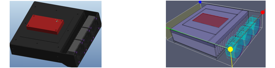
3pcs 6025 fans, 5mm to the front panel, the corresponding open area ratio on the panel is 65%, aluminum extruded heat sinks are used, Thermal interface material: 7762 grease 0.1mm, K=4W/m*K.
Descriptions of fan usage and parameters:
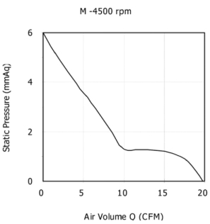
C6025M12BPLB1w-7 fan was used in the initial design
(Parameters: 12V, 4500RPM, 34.13dBA)
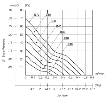
NMB2410ML-04W-B80 is used in our solution
(Parameters:12V, 7800RPM, 46dBA)
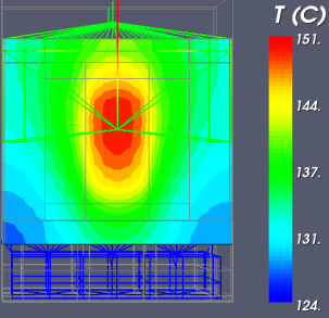
Schematic of the simulated temperature profile with the initial design fan:
Schematic of the simulated temperature profile with the new fan in our solution:
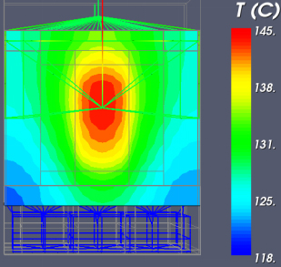
(Simulation results indicated that for the original heat sink with C6025 fan, the IGBT case temperature is 151℃. For our proposed solution with the NMB6025 fan, the IGBT casetemperature is 145℃. Both fans have the same fan speed, noise, voltage, life expectancy. Therefore, this NMB fan will be the first choice.)
Schematic of the simulation results of the air cooling solution for PV inverters and the summary of data:
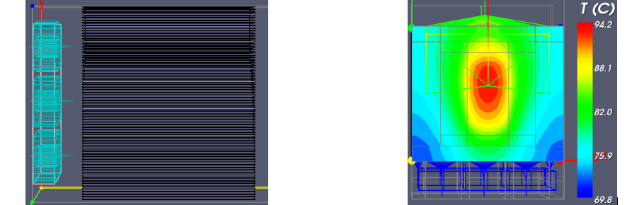
Summary of data:
(1) This solution uses all aluminum skived fin heat sink with NMB6025ML 7800RPM fan. The heat sink profile and size remain unchanged. The base thickness remains unchanged. The fin thickness is 0.8mm with a total of 73fins and the gap is 2.3mm on the skived fin heat sink.
(2) Caution: It is required to adjust the fan location so that there is no gap between it and the front panel in an attempt to avoid air recirculation. (The original design has a 5mm gap, which causes air recirculation and the resulting temperature is 6℃ higher.)
(3) Simulation results: The IGBT case temperature is 94.2℃, which meets the customer requirement of 100℃ or below.