Inverters are also called power regulators. The process of converting DC power into AC power is called invert. The circuit that can realize the inverting function is called an inverter circuit. A device that can realize the inverting process is called an inverting device or inverter. In a solar energy generation system, the inverter efficiency is an important factor that determines the solar cell capacity and the storage battery capacity. The breakdown of PV inverter will cause the PV system to shut down and this directly leads to the loss of power generation. Therefore, high reliability is an important technical indicator for PV inverters.
The good cooling of PV inverters is an important criterion to ensure the high reliability of its operation. Therefore, it is recommended to carry out thermal simulation in the beginning of PV inverter's design stage and this has become the first issue to be considered by PV inverter manufacturers. As one of the professional high power cooling manufacturers in China, Winshare Thermal has an outstanding thermal design and development team, which owns the capability of carrying out reliable thermal simulation and testing. We have collaborated with several domestic and overseas PV inverter manufacturers on the cooling technology for inverters and have been supplying services and supports with our professional cooling technology.
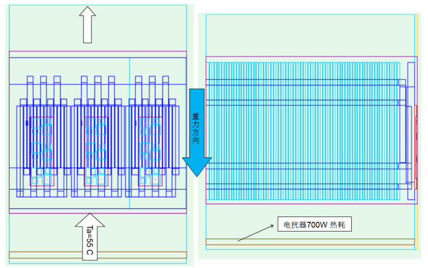
Schematic of the simulation model and parameters (1):
Ambient temperature: 55⁰C; reactor heat load: 700W
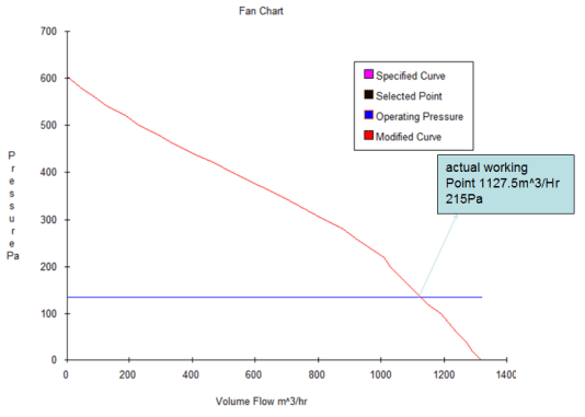
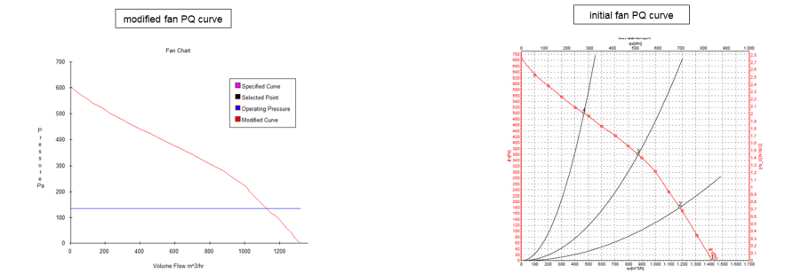
Assuming a system impedance of 80 Pa, the fan curve through the heat sink can be adjusted as follows.
Schematic of the simulation model and parameters (2):
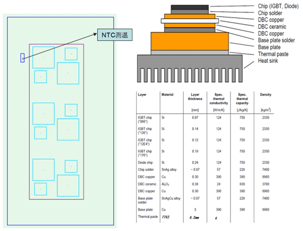 The top left figure is the schematic of the internal structure and heat-dissipating devices of the Infineon IGBT
Diode:59W; IGBT:124.5W; Total:1100WW;
Assuming the thermal interface material is 0.15mm thick with a thermal conductivity of K=3W/m*K
Schematic of the simulation model of the heat sink solution and its parameters:
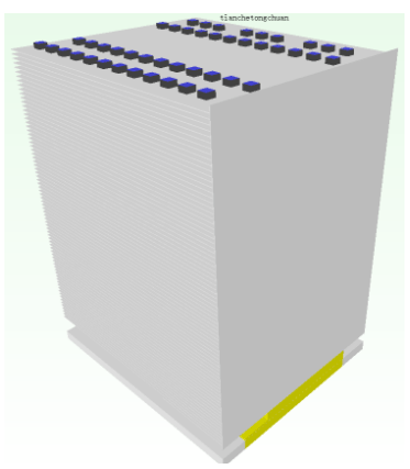 Heat sink parameters:
Dimensions: W236*L200*H304mm
Fin :
Thickness: 0.6mm
Fin gap: 3.0mm
Fin count: 77fins
Heat pipe parameters:
DD8 sintered tube or groove structure;
24 pcs of U-shaped heat pipes (single-layer layout) and 48 pcs of L-shaped heat pipes (dual-layer layout) are used
4258 low-temperature solder paste is used for soldering;
Base: Al plate + copper plate (IGBT heat source area)
The design with a single layer of heat pipes has a lower cost and higher cooling performance as compared to dual layers of heat pipes.
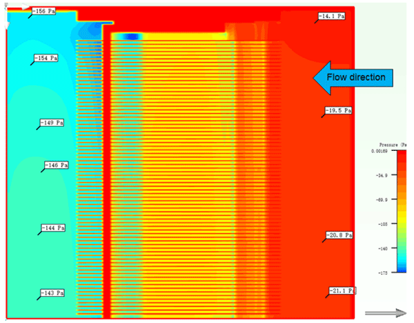
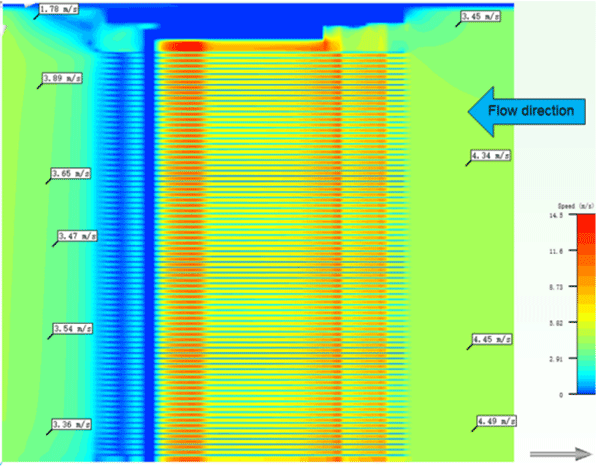
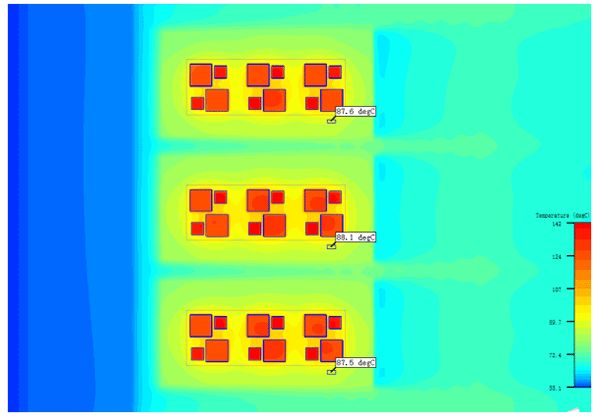
Schematic of the simulated cross-sectional temperature distribution in the thermal module:
Schematic of the simulated temperature distribution on the top layer of heat pipes:
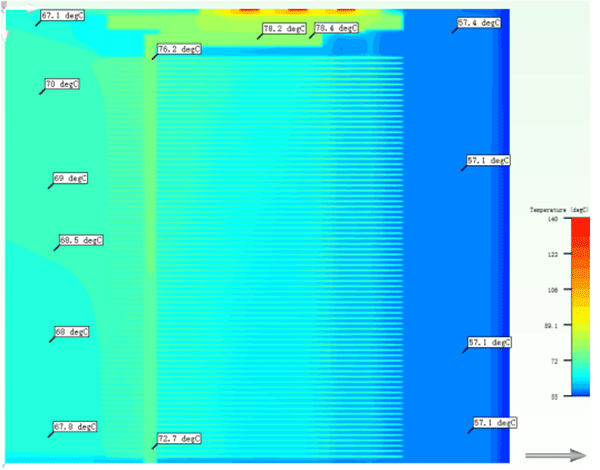
(The temperature difference between both ends of the heat pipe is 5.7℃, which meets the practical criteria for heat pipes.)
Schematic of the simulated temperature distribution on the bottom layer of heat pipes:
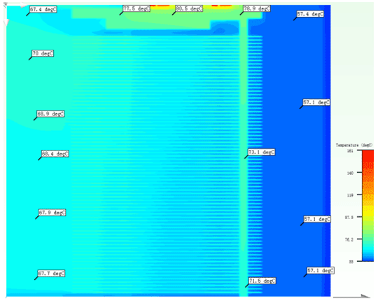
(The temperature difference between both ends of the heat pipe is 9℃, which is slightly higher than the real scenario. The actual performance of the heat pipes will be better than those configured in this analysis.)
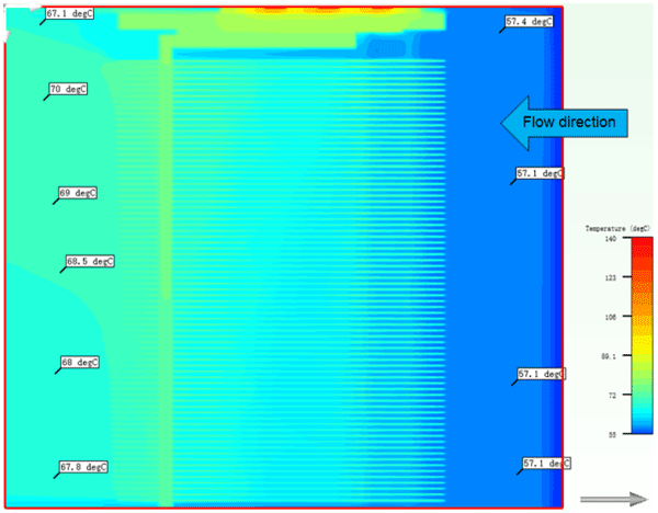
Schematic of the simulated temperature distribution on the bottom side of the heat sink:
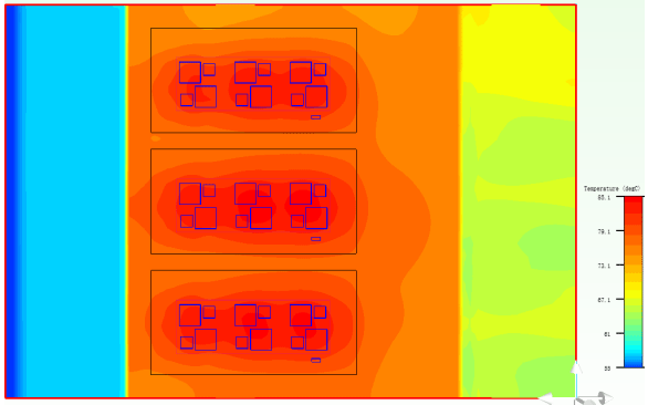
(The actual air temperature entering the heat sink is ~57.1⁰C and the maximum temperature at the heat sink bottom is 85.1⁰C with a temperature difference of 28⁰C according to the theoretical analysis.)
(The temperature difference between both ends of the heat pipe is 9℃, which is slightly higher than the real scenario. The actual performance of the heat pipes will be better than those configured in this analysis.)
Assuming a system air inlet temperature of 55⁰C, the temperature of the air leaving the reactor is 57.1⁰C. Assuming a thermal interface material of 0.15mm thick with a thermal conductivity of K=3W/m*K is used.)